This installation explain quickly how to install iDE Resurector to use with IDE to SD adapter.
For a great tutorial you can check Tito’s video, and mines on my Youtube Channel, links below.
Important: please keep in mind that this is only one possibility, the installation with an SD card converter.
Other variations are to come with a SATA adapter to connect an SSD or HDD, externally to keep the optical drive, or internally but removing the optical block. 3D models to print will also be proposed.
In reassembly process, you do not have to put the back plate back on. On the top plate you have to slightly raise a leg of the metal plate where the flex passes to avoid short circuit.
To replace the back plate, you can use washers you can find here: 3D parts to print
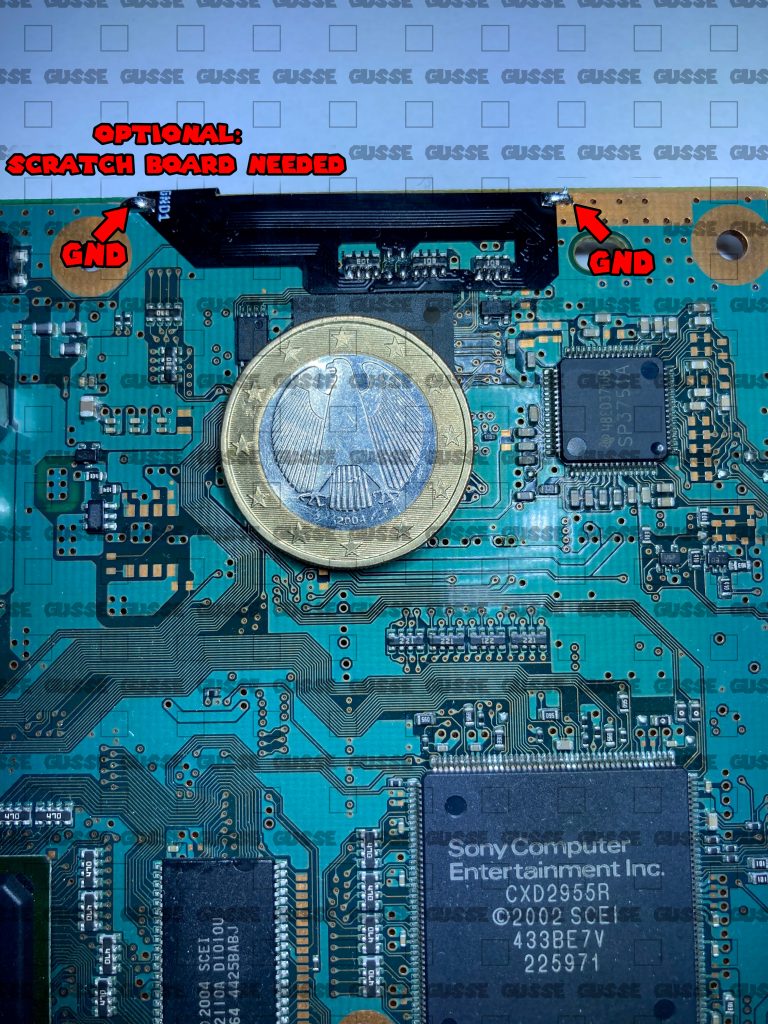
1. Solder the flex on the top side of the motherboard
position the flex to align it with the components as shown in the photo next to it.
To help you: if you are right-handed, start soldering from the left, if you are left-handed start from the right. It is very simple, it avoids you to pass on solderings that you already made.
Do not hesitate to use a lot of flux, it facilitates greatly the task.
Be careful not to stay too long on the solder, the flex is heat resistant within reason 😉.
Make solder on the GND of the motther to maintain the flex on the board
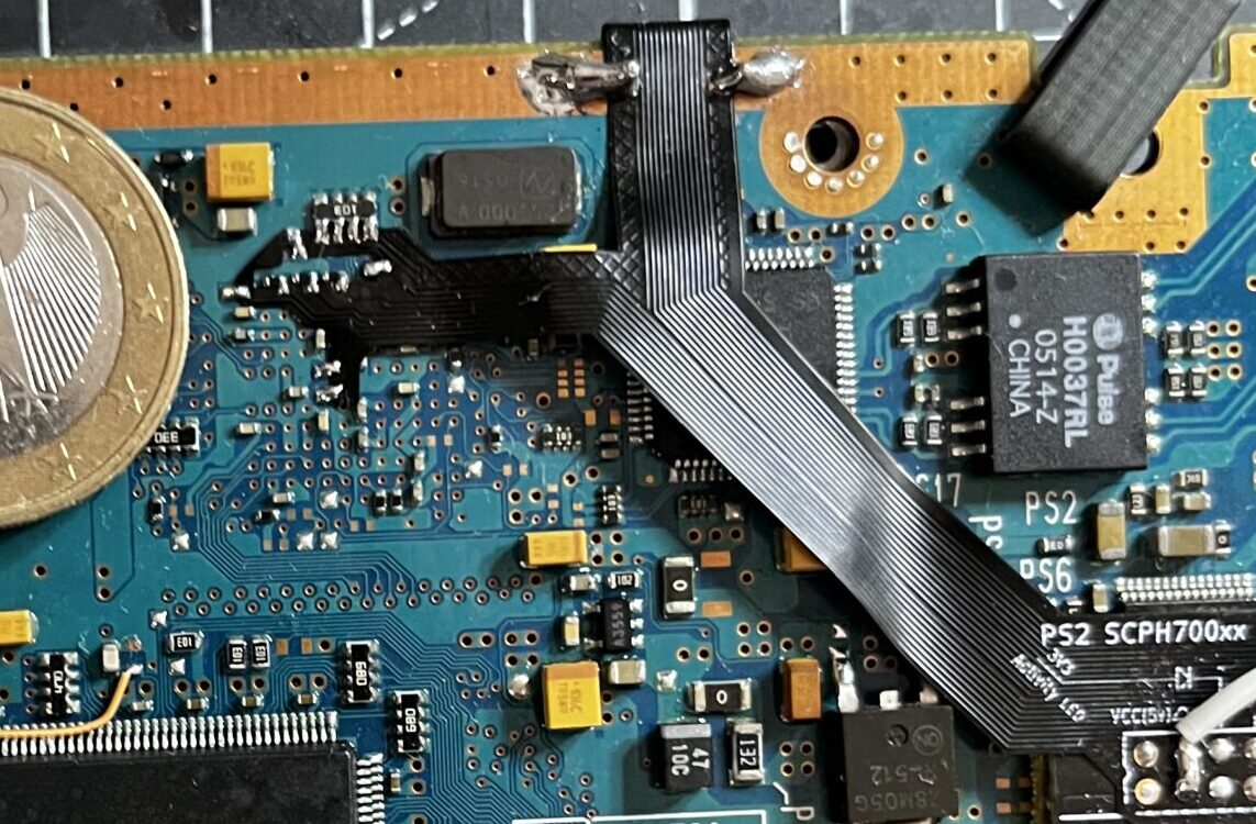
2. Solder flex on the bottom of the board
You can use kapton tape to hold the flex, take your time.
Tip: make a soldering point on the resistance board and one at the bottom then press with a pliers or a tool to put the flex as flat as possible, check the alignment before making too much solder.
Check next step for 5V connection
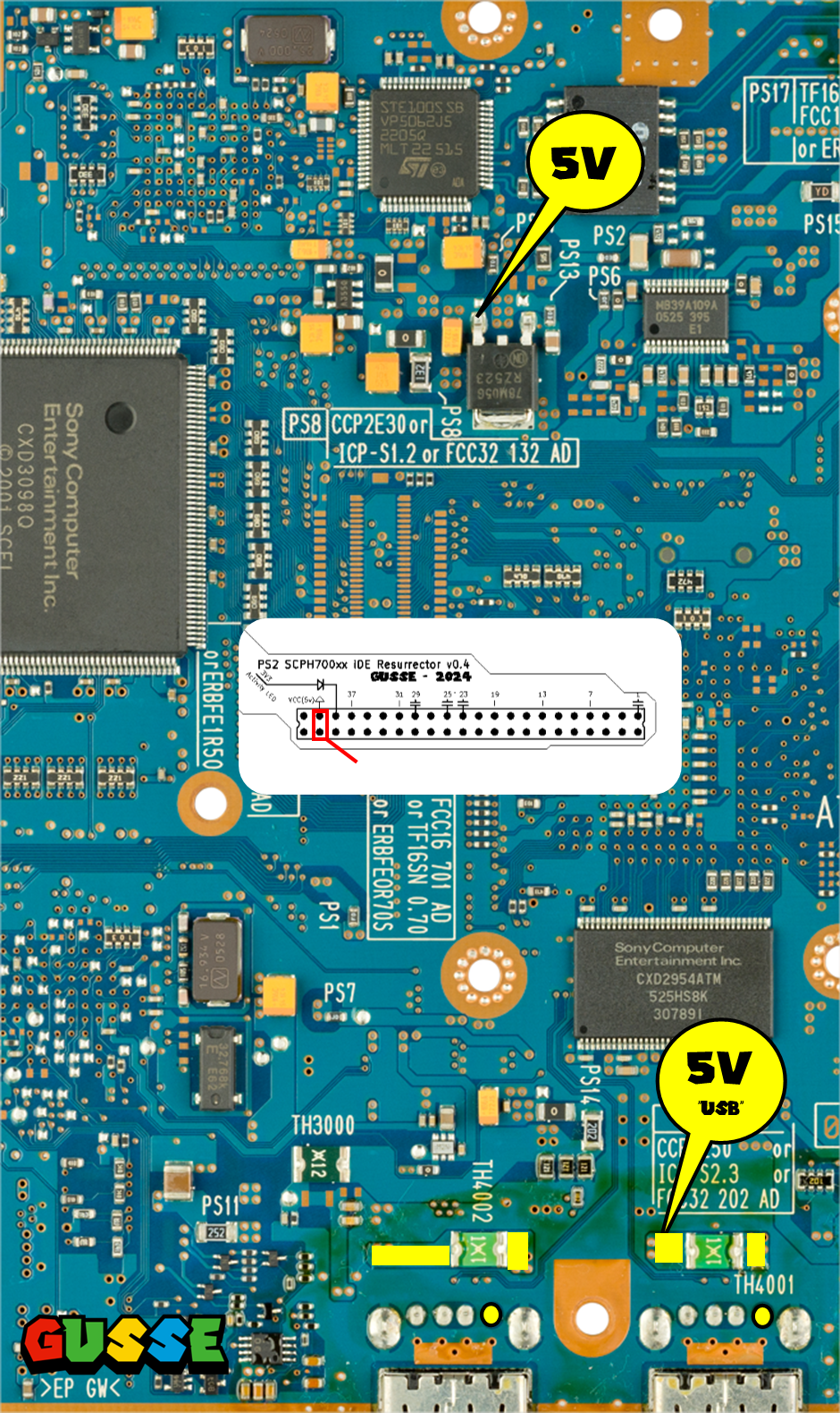
3. 5V connection
Solder 5V wire (not supplied) directly to the indicated connection points.
– For SD Card Mod Use voltage regulator near the flex
– For SATA Mod / SSD / HDD / M.2 Use 5v from USB or top of the board
Yellow shape are alternative point for 5V USB.
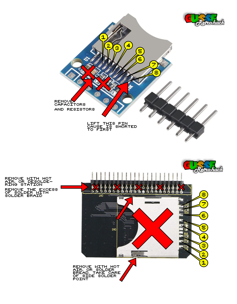
4. Prepare and solder to micro SD
To thin and close your console, you must remove the pins of the IDE to SD converter, use a hot air station, or a desoldering pump, or braid etc …
To maintain the SD converter you can scratch the motherboard and make a holding tab (see my youtube installation videos).
You can also wire the activity led behind the adapter by under the activity led and soldering wires to then move them to the front of the motherboard.
Remove all components on the micro SD connector.
On the micro SD connector, lift the last PIN, because on this kind of adapter, pins “1” (3 if we count the useless pins) and 8 are connected, while we need them to be separated, and isolated so that after reassembly there is no contact.
To put it simply, you have to solder on the raised leg, not on the PAD, the PAD must be isolated from the circuit.
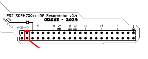
Connect your wires according to the diagram on the side, and connect the wires well on the legs and not on the pads.
5. Troubleshoot guide
If installation doesn’t work as intended, you can check here the troubleshoot guide to find some resources to try to manage to fix your trouble: troubleshoot guide
