This guide will help you install the PS2 Slim Methylene – Complete (version with ESP32).
The process of soldering the ESP32 to Methylene is simple a simple solder pad, you can drag the solder if you’re confident enough, but be aware of potential shorts, so double check your work. If you’re a beginner, you can proceed stitch by stitch and TAKE YOUR TIME 😉.
In this guide, I’ll assume that you have your PS2 Slim board in your hands, as you’ll find some excellent disassembly guides on the Internet.
The guide may seem long, but installation is relatively quick (about 15 minutes).
NOTE: If you’re using a SCPH900xx, installation is doable, but the space under the motherboard is very tight. I advise you to remove the ESP32’s metal shield to free up some space.
Before starting installation, I recommend that you first read this guide in its entirety, then follow it step by step during the installation.
You can find installation videos here (with old revision but same principle) :
https://youtu.be/p2AAjnSoD7s?si=mXjJyEjHpQ8B3bp8 (from my Youtube channel)
https://youtu.be/aY2O5fLIWDw?si=A58GERt7nuepp91K (courtesy of Atherismods)
Please note: that these videos are based on the early flex versions of Methylene, which required more preparation to install properly. The new version of Methylene doesn’t require as much preparation to flatten the board.
1. If you plan to use wireless controllers ONLY AND don’t make PIN5 isolation
If you wish to use ONLY wireless peripherals with your console, you do NOT need to isolate pin 5 as shown in later steps.
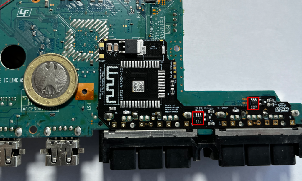
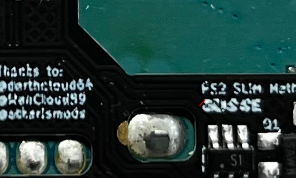
In addition, you DO have to remove the two components shown on the following picture OR cut the trace shown. This can be done using either a hot air station, or hot plate.
If you don’t do that, you can get bad behavior during use of Methylene.
2. Preparation for wired controller detection
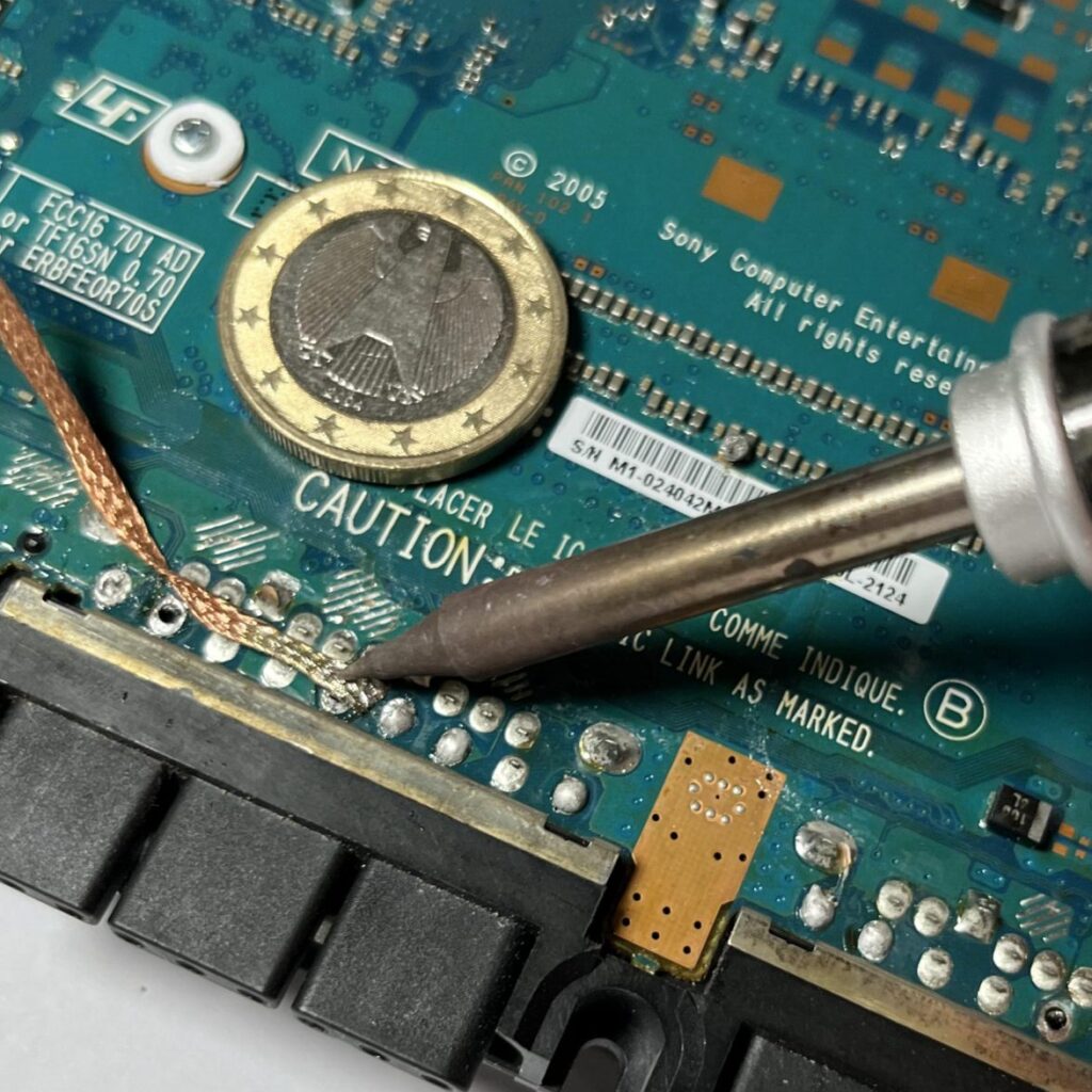
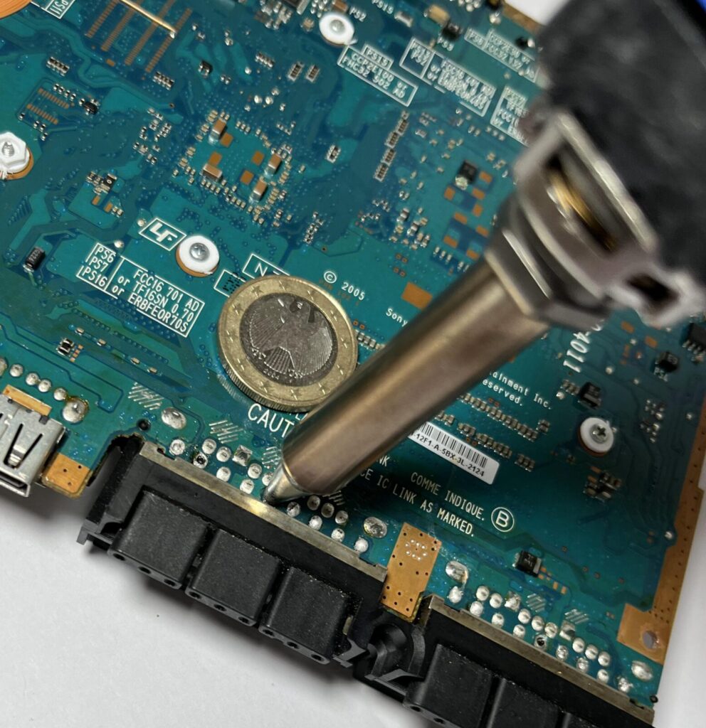
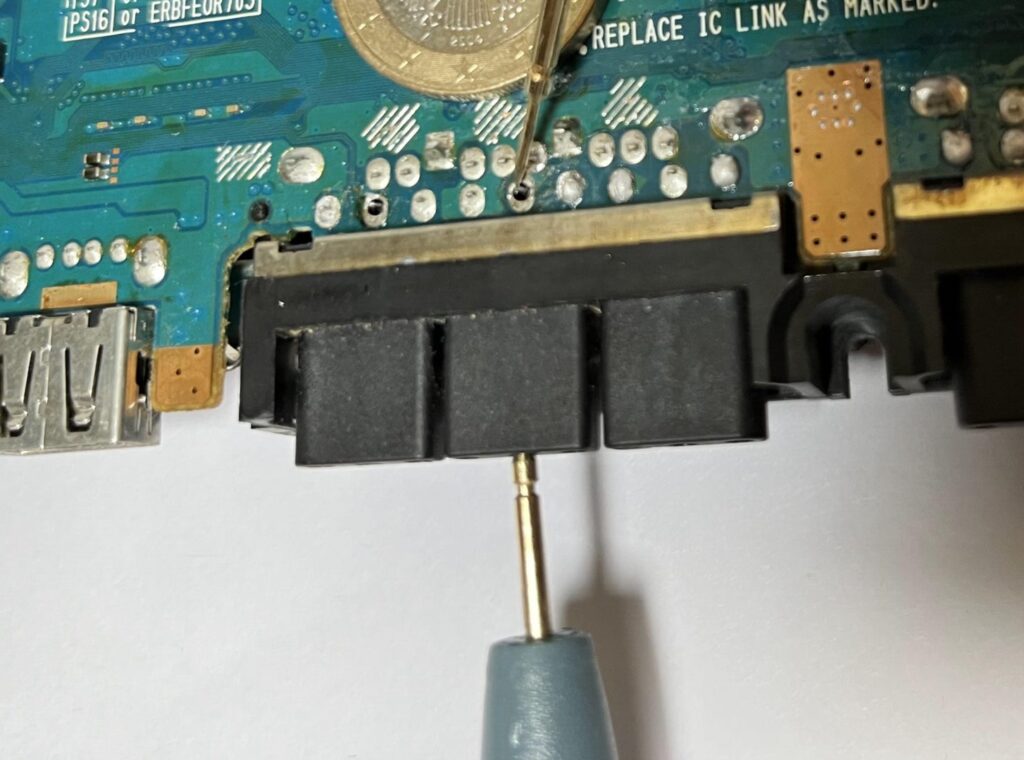
We start with the most technical part of the installation. This involves electrically isolating 2 pins of the controller connectors from the motherboard. According to my tests, there’s no way of just cutting a trace of the motherboard, so this operation is necessary to use wired controllers to avoid interference when using your console.
It consists in removing the solder from PIN N°5 of the 2 controller ports.
The aim of this operation is to break the contact of this connection, so that the port’s power is routed through Methylene and no longer through the console.
There are several ways to do this, depending on your equipment:
- use desoldering braid and your soldering iron
- use a desoldering pump
- use a desoldering gun (the best solution in my opinion, but the most expensive if you don’t have the equipment)
Once the desoldering operation has been completed, check the continuity between the motherboard and the pin. Normally, there should be no contact, but if not, repeat the operation until there is no contact.
Optional/recommended: Once this is done, you can add UV paste or glue to hold the pin 5 in position and avoid unwanted connections.
3. For Methylene BASIC versions only
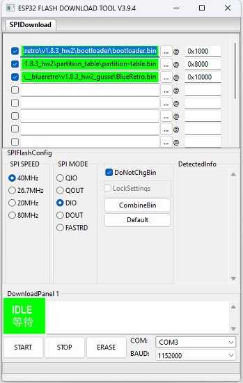
Flash the ESP32 using your external programmer, or use an ESP32 already flashed with blueretro, and you’ll be able to update it by OTA update via bluetooth.
You’ll find an excellent tutorial on this on Blueretro’s Github repo at this address:
https://github.com/darthcloud/BlueRetro/wiki/Flashing-firmware-Windows-10
A link to get Blueretro (bootloader.bin and partition-table.bin):
https://darthcloud.itch.io/blueretro (please make a donation to the team behind this great work)
The modified version of Blueretro v24.11 for Methylene
Blueretro HW2 – Methylene edition
Changelog :
24.11 (based on 24.04 official release)
– wired controller detection logic reviewed, controller detection only occurs when console is ON
24.09 (based on 24.04 official release)
– Dualshock 3 bugfix in specific case
– Rumble enabled by default on flash
Once your ESP32 is flashed, all you have to do is solder it to the corresponding pad on the flex.
OR with new structure (both are compatible) :

4. Solder board to controller port pins
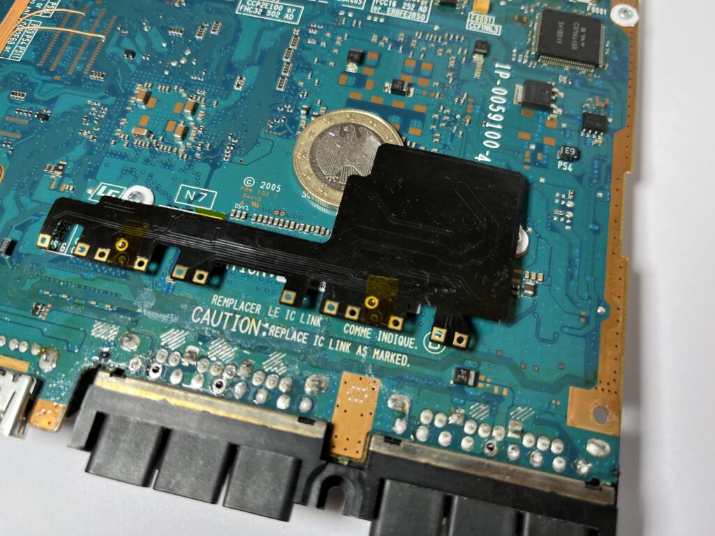
Check the alignment of Methylene with the connection pins. If the board is well positioned, it should hardly bend at all. If it does, check that nothing abnormal is happening underneath, apart from small capacitors which are tolerable above port1.
Be sure to solder all GND anchor points similar to those shown in the illustration.
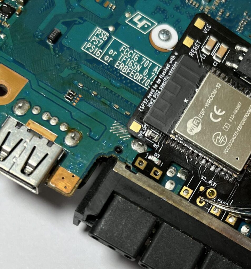
ATTENTION: make sure you solder the 3v3 point shown in the photo opposite, it’s small enough to avoid coming into contact with other traces, the soldering is done on the edge and slightly on the top, it’s easy to do.
When the board is aligned, tack the first weld to align, then another at the end, and then weld all the points.
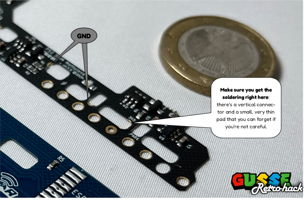
If you want your board to lie flat, you can lightly scrape your motherboard in these areas to make anchor points and soldering points to keep it perfectly flat.
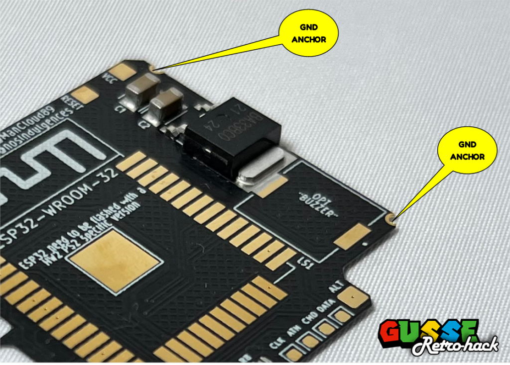
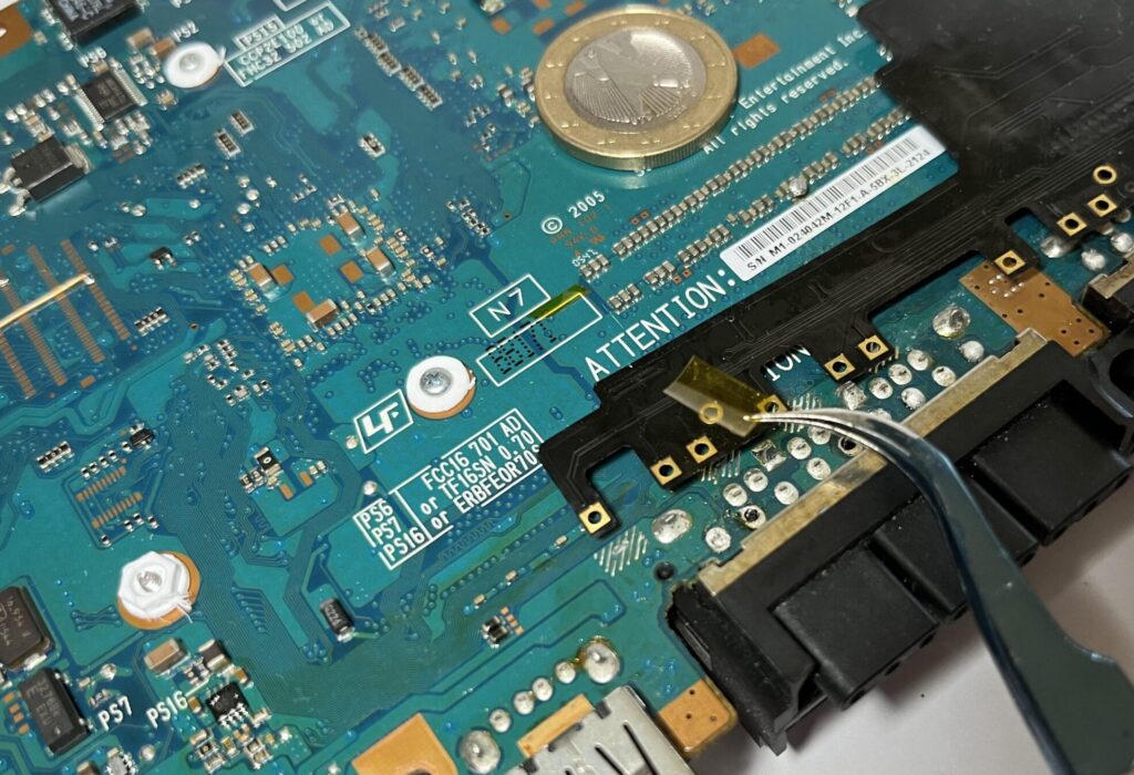
Beware of the specific connection detection point: although it’s isolated behind the board, it’s advisable not to overload it with solder to avoid coming into contact with the motherboard, and to be in good contact with the pin that comes out.
TIP: you can stick on a piece of kapton tape, and pierce it with the detection pin to solder without worrying too much about a possible connection problem.
5. Soldering the power supply wire
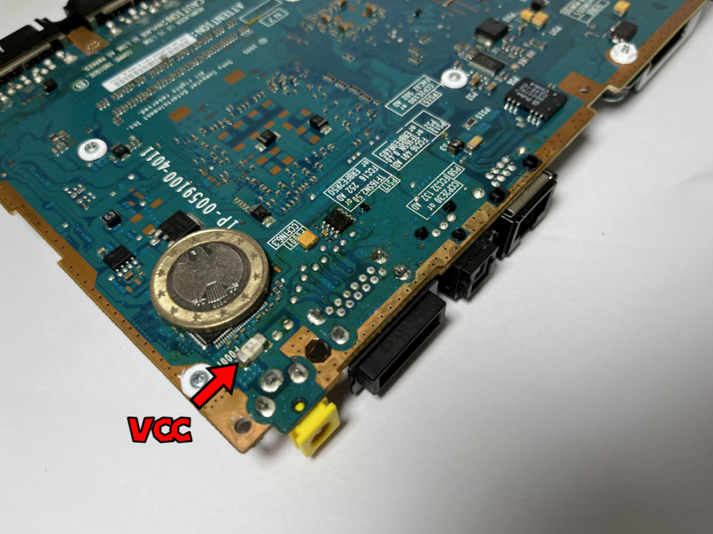
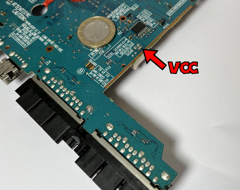
Solder a wire from the fuse labeled F0001 near your console’s DC jack to the PAD named VCC on Methylene (check instructions below).
I recommend using at least AWG26 wire.
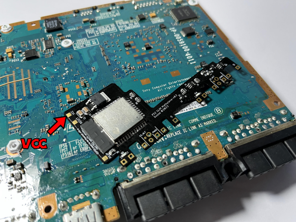
For SCPH70xxx, SCPH750xx, SCPH770xx boards
Solder the wire just after the fuse named F0001 next to the console’s power port.
For SCPH90xxx boards.
Solder the wire on the power connector pin
6. Solder the reset point
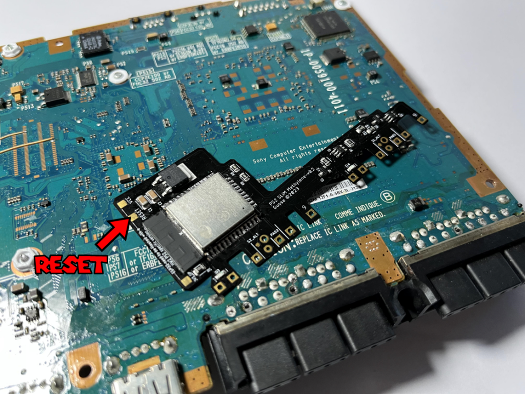
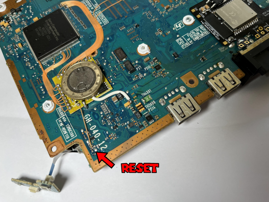
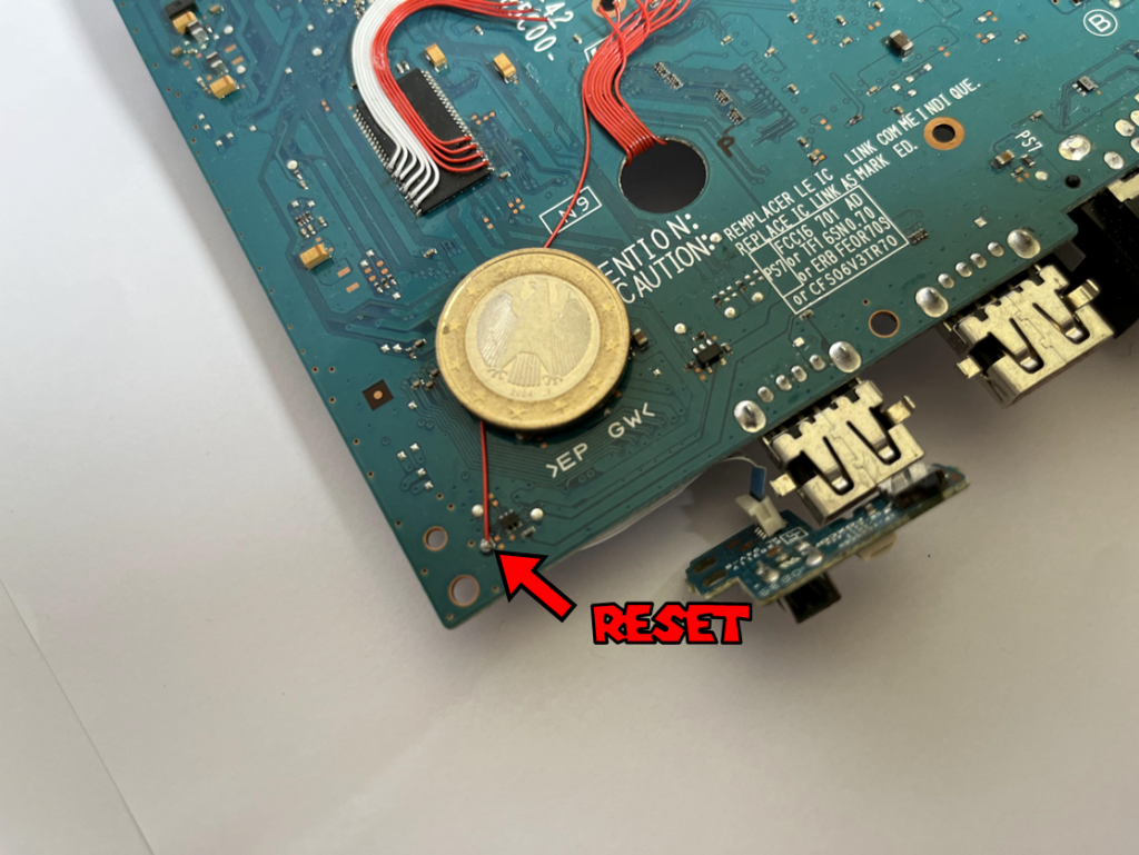
Solder a wire from the RESET pad on the board to the reset point on your console, the same one used by the m0dch!ps.
If you have a modchip, you can solder to the RST point on your chip, taking care not to unsolder the wire already in place.
You can consult the bullet diagrams on my site to find the reset point, which is generally located at this point.
7. Final result
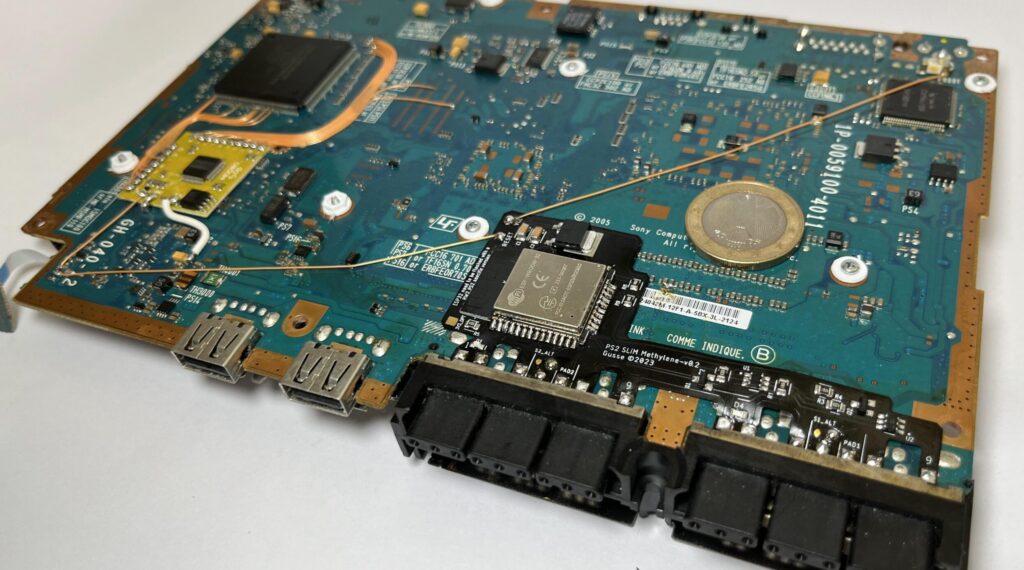
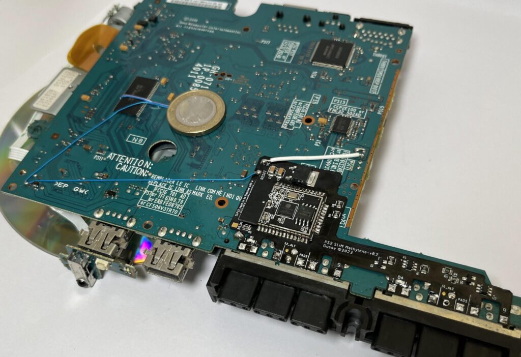
Once installed, it should look like this.
WARNING: on SCPH7xxxx, I don’t recommend replacing the metal shield. To hold the front plate in place, you’ll find washers available for 3D printing here, or get 2mm-diameter nuts for the console screws.
7.1 Final result
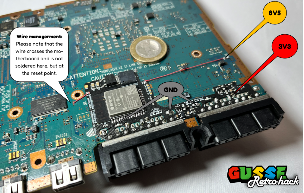
Here’s a photo of the final installation on a v12 with optimized wire management. This is not possible on all revisions. I used the alternate power point to shorten the wires. The wire is soldered to the left of the PS15 fuse. The reset wire passes over the top of the motherboard and THROUGH the motherboard, if you do this make sure your wire is well insulated.
8. Start-up and pairing
Now that installation is complete, you can connect your console to the power supply. LED 1 should flash when connected.
Start your console by pressing the power button on the console. The ESP32 is now waiting to be paired with a joystick; the LED on Methylene pulses slowly.
Perform the pairing operation specific to your controller, e.g. on Dualshock 4, hold down SHARE+HOME until the LED on your controller flashes rapidly until it turns to a fixed color to indicate the success of the pairing, and the LED on Methylene will also be solid.
To pair a second controller, switch off your console and carry out the same procedure with another controller.
9. Wired controller detection
To test this functionality, I recommend using a Bluetooth controller with an indicator light.
For example, a Switch Pro controller or a Dualshock 4.
Pair up your controller and boot up the console.
Then connect a wired controller to port 1, and the position of your Bluetooth should change. For example, your Dualshock 4 will turn red, or a Switch Pro controller will switch to position 2.
