In this guide, you’ll find some information to help you diagnose your system in the event of a problem.
Diode value, measured with the red probe on ground and the black probe on the iDE connector side, values may fluctuate slightly from one console to another. These values were measured with a SATA adapter and capacitors installed, values with an iDE to SD adapter should be very close. If a value is different, check your soldering.
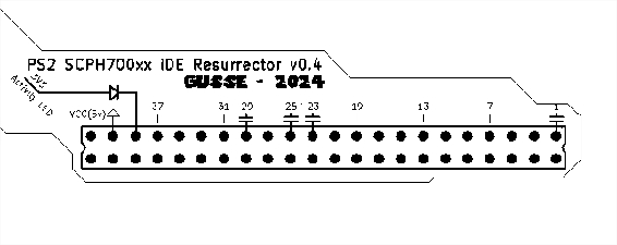
You can help with indicated PIN value on iDE resurector to count PIN:
| Pin | Diode value (V) | Ohm value | Pin | Diode value (V) | Ohm value |
|---|---|---|---|---|---|
| 1 | 0.563 | 2 | GND | ||
| 3 | 0.558 | 10k | 4 | 0.558 | 10k |
| 5 | 0.558 | 10k | 6 | 0.558 | 10k |
| 7 | 0.558 | 10k | 8 | 0.558 | 10k |
| 9 | 0.558 | 10k | 10 | 0.558 | 10k |
| 11 | 0.558 | 10k | 12 | 0.558 | 10k |
| 13 | 0.558 | 10k | 14 | 0.558 | 10k |
| 17 | 0.558 | 10k | 16 | 0.558 | 10k |
| 19 | GND | 18 | 0.558 | 10k | |
| 21 | 0.554 | 4.7k | 20 | NC | |
| 23 | 0.562 | 22 | GND | ||
| 25 | 0.562 | 24 | GND | ||
| 27 | 0.527 | 1k | 26 | GND | |
| 29 | 0.560 | 28 | GND | ||
| 31 | 0.560 | 10k | 30 | GND | |
| 33 | 0.560 | 32 | NC | ||
| 35 | 0.560 | 34 | 0.742 | ||
| 37 | 0.560 | 36 | 0.560 | ||
| 39 | 0.692 | 38 | 0.561 | ||
| 41 | 0.105 | 40 | GND | ||
| 43 | GND | 42 | 0.105 | ||
| 44 | NC |
Check continuity
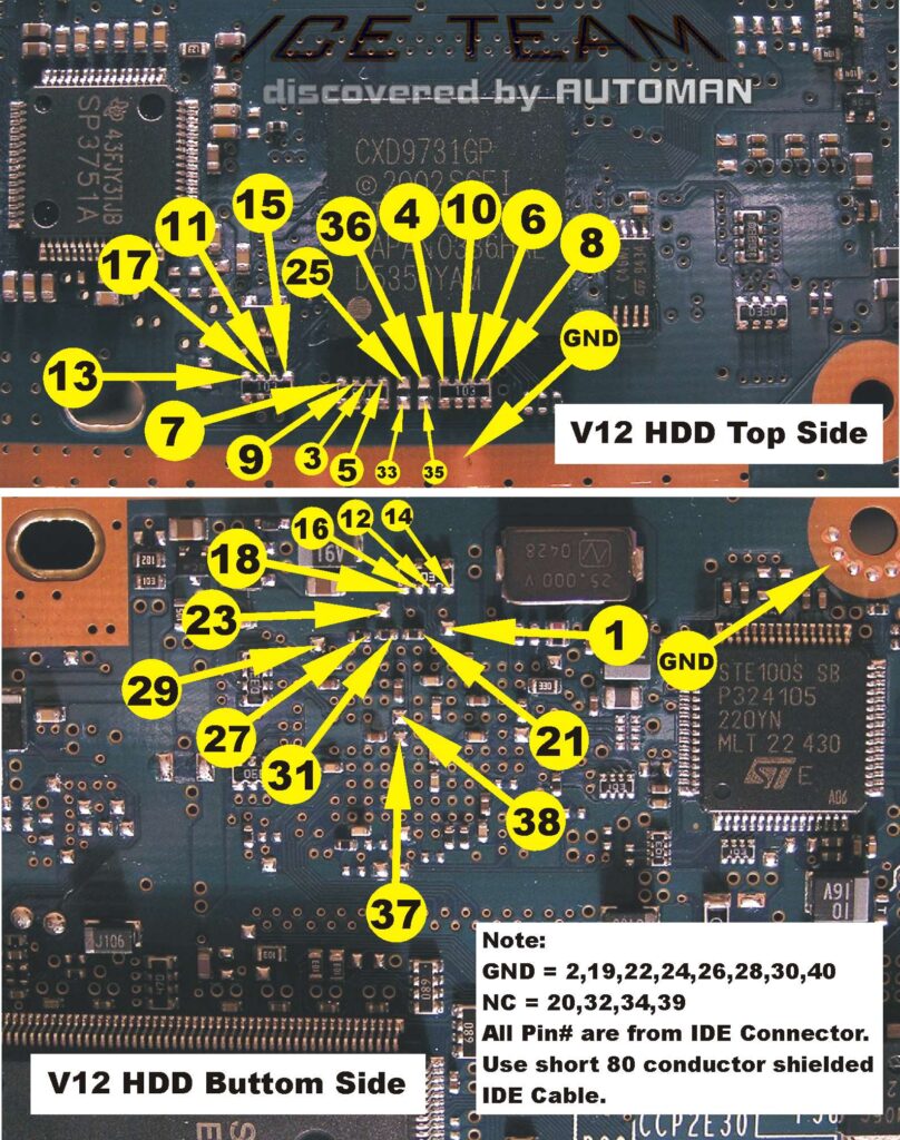
According to the original schematics from Ice Team / Automan (a big thank to them), check each point from motherboard to adapter, use Pin indication on flex to help to count Pin.
Also check adjacent PIN together, sometimes a solder splash could appear under the board or under the flex.
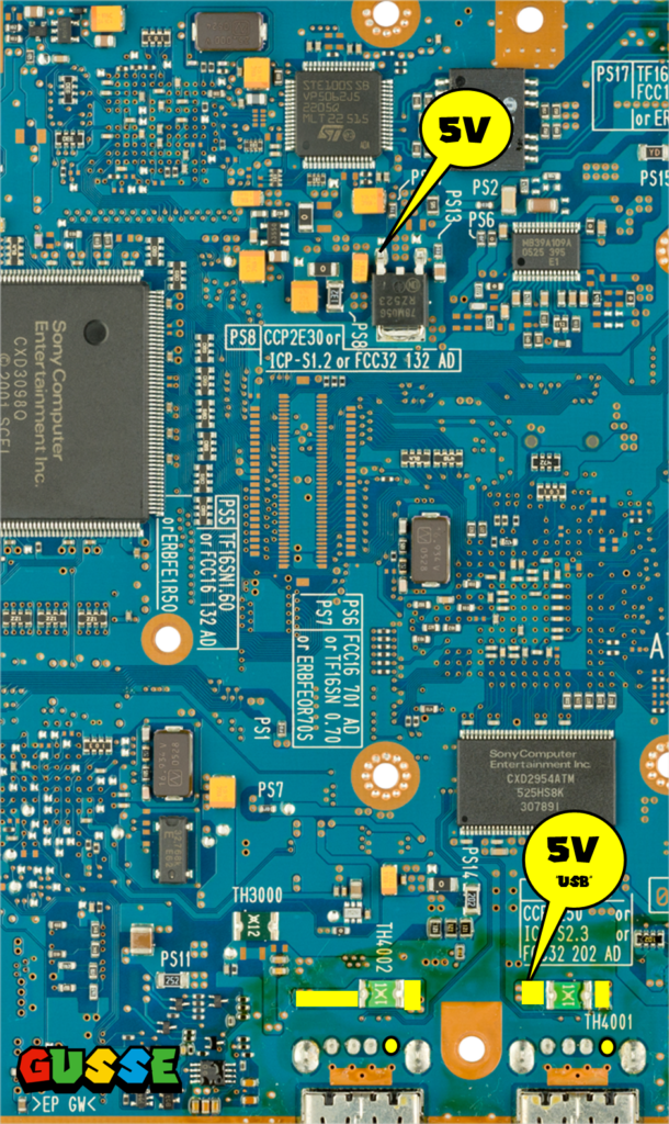
Check voltage
Depending of your installation (SD Card mod or SATA) you can check 5V according to the diagram below.
If you made a SATA Mod, you must 5V from USB port (5V1 to be precise).
If you don’t have 5V, the nearest regulator or fuse may have blown.
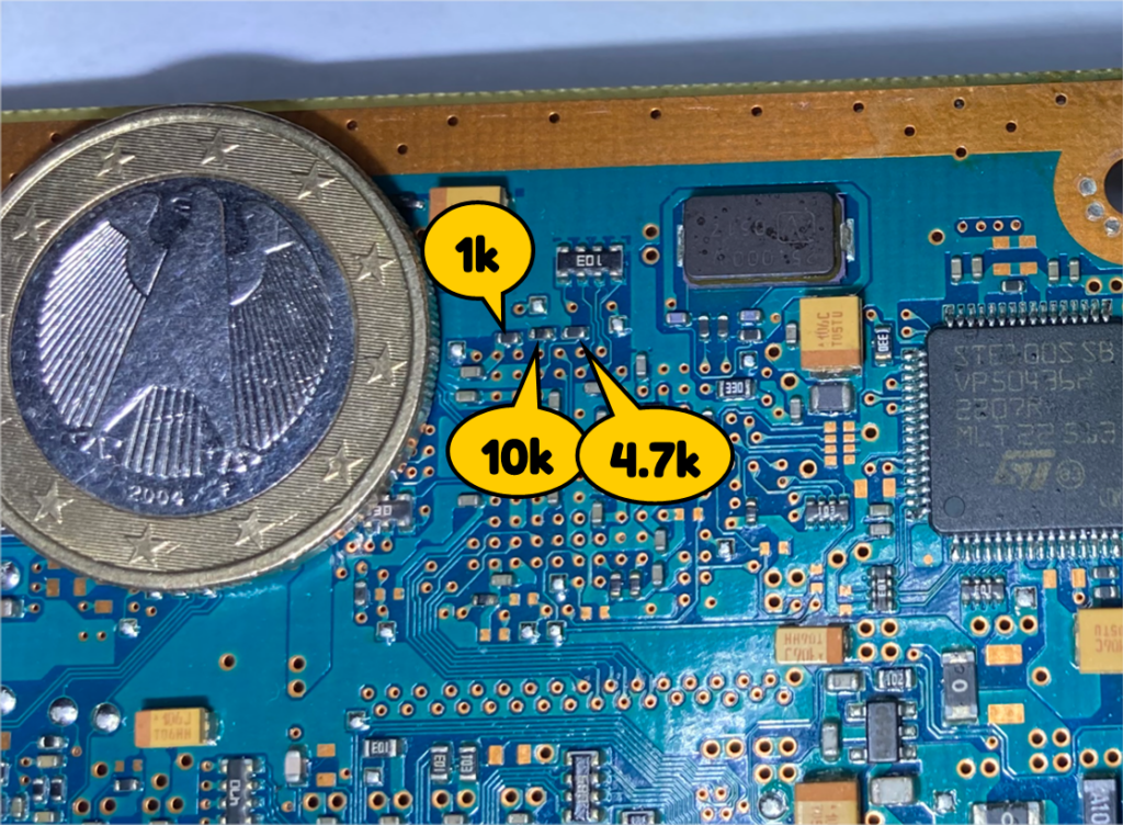
“Lost components”
If you have lost some component during installation, here is the value of some component on diagram below: